1: High Speed Photography – and more

(Latest update October 2018)

My slightly more unusual pictures are created using a number of home-made gadgets… well, I shall call them “technical devices,” which sounds a lot more impressive!

After many (ok, a few) requests along the lines of “how did you do that,”  I’ve decided to outline the basic techniques here. Click “About” in the header to see what’s coming…

First some examples, to either whet your appetite or steer you away:

1_1_grape_shot_dropsy_1
1_2_cherry_drop
1_3_wgg_sacrifice
1_4_crash_site
1_5_whoosh_plus

or just for for fun, the beginnings of playing with light-painting:

1_6a_zapped1_6b_xmas_lights1_6c_and_10_4b_emergence1_6d_and_10_4d_betty_lp_1
Soon to come: some experiments with water-droplets…
fxd IMG_2032 crop 1024
aa IMG_2041 (2)

2: Basic Methods

Or, how the pictures in Post 1 were made….


First of all, I’m not purporting to be any kind of expert – I only took up photography after I retired and bought my first ever camera in the autumn of 2007. I have learned everything I know from other kind photogs who were willing to share knowledge and ideas, mostly via the Flickr picture sharing site. This is just about paying it forward… and of course to give a chance for people who know better than me to comment and offer suggestions, corrections and better ideas!

A couple more examples// “timing is everything”


2_1a_timing_is_everything2_1b_crisp_and_dry


The Basic Approach

The high speed pictures capture an event (such as a cherry splashing into a bowl of cream) with a very short exposure time. Usually, the “impact event” is too fast for the normal shutter speed of your camera. In the case of the popping balloons, eggs shot by arrows or air pistols, and so on, you would need a much shorter exposure time than a shutter can provide if you want to freeze the motion.


The most common trick is to use a flash unit. The xenon (eg “speedlight”) flashes can often have their power output turned down (in manual mode) and they do this this in a very helpful way. Instead of reducing the intensity of the flash, the duration is reduced. So at half power, say, the flash is “quenched” when half the normal amount of light has been emitted. At 1/128th power, the duration of the flash is somewhere around 1/30,000th of a second. Even quicker according to some sources. That’s short enough to freeze the “explosion” in all the pictures above. It won’t freeze a bullet in flight, but it will freeze the explosion that the bullet-strike produces. Pretty much 🙂

So this is how it works: Set up the event (fix the target, aim the.. crossbow in my case) then turn the lights off. Open the camera shutter for a few seconds, and fire the flash – at low power – just as the impact occurs. That, of course, is quite hard. Even with a cherry drop or a water drip – relatively low-speed events –  getting that timing just right is quite a job, and I’ll explain how I do this in what follows. The important thing is that the only light reaching the camera is from the very short flash, so it’s like having a super-fast shutter speed.

You could TRY and fire the flash at just the right time, but the odds are you will have to do a lot ( a proper LOT) of tries to get the shot! The solution is to make or buy an event-trigger that can fire the flash for you at just the right time. For example, a sound trigger picks up the bang of the crossbow/pistol firing, or an infra-red beam is broken by a falling cherry. If you then use a (simple) circuit to add a slight – and adjustable –  delay between the triggering event and the flash, you can take the picture at JUST the right time. Job done!


You can connect the output from your event trigger/delay unit to your flash by cable, but it is much more convenient if you use a wireless flash trigger. This especially applies if you want to fire more than one flash unit – which is often a good idea since 1/128th power means a short but not very bright flash. Also, you may want a second or third flash to light up a background or something.

It can get a bit confusing if you are new to this, since the wireless flash triggers are often just referred to as “flash triggers” and the event triggers are too.


Ok, so my setup is:

  1. a sound or optical trigger that is activated by the “first event” (gunshot, dropped cherry)
  2. a delay circuit that counts a tiny fraction of a second then fires the…
  3. wireless flash trigger tansmitter – connected to the delay unit. This immediately (pretty much) activates the…
  4. wireless flash trigger reciever(s) which are connected to and fire each flash unit.


Remember, while all this is going on, the room is dark and the camera shutter is open – on ‘bulb’ for example. After the flash, the shutter closes and smiles all around. Sometimes 🙂

Lights (off), Camera (open shutter), Action!

Here is my first (home made) bit of kit, showing the sound trigger (grey box), delay unit (black box) and wireless transmitter: as used for the egg picture in Post 1.

2_2_sound_trigger_kit


The circuit designs here are all courtesy of HiViz (www.hiviz.com) Their website is a treasure trove!

For some (slower) events, I have used a wireless shutter release (yes, a third type of trigger!) to operate the camera shutter, and let the camera operate the wireless flash transmitter. But the latency (built-in delay) in getting the shutter to fire that way was already way too much for the fast events using the crossbow or a balloon pop. Probably the fault of the wireless shutter release, to be honest, but the method described here lets me set the delay completely using the little black box…

You’ll note in that picture that my kit is in neat boxes: after realising that this was SO much fun I decided to make a more permanent job of the circuits. The boxes and sockets cost two or three times as much as the electronics inside. Not kidding! And I had a few of the sockets lying around from other projects. Sound trigger circuit : Parts cost about £5 (GBP) – about $7US I suppose – without the fancy box, and it works just the same. HiViz sell a kit, with a box and all parts for $29 [Oct 2018]

3. What about these triggers then?

A quick overview of what is available… updated October 2018


So, we need a small and preferably cheap electronic gizmo that will be triggered when an event such as a passing cherry or a popping balloon occurs.  We need it to then fire a flash unit, or  even the camera shutter for slowish events like a bird taking off. (The camera can then fire the flash in the normal way that cameras do!)  The range of triggers – and sensors for the various types of event –  is quite extensive now.

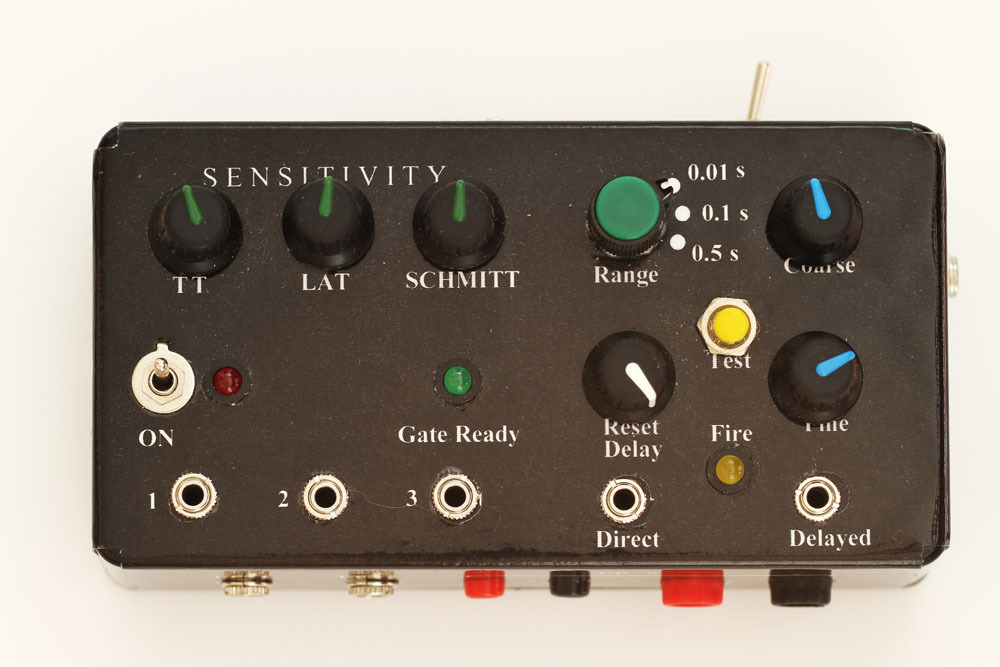
You can make your own, buy a kit, or buy a ready-made system.  I went with home-made, and not just because I’m cheap!  For me, part of the fun is in the making, seeing what I can do for myself:  More details of mine in Episode 4.

This isn’t a comprehensive list, and do send a message if I’ve missed a helpful link, but the commonly discussed triggers include these:

1.    Make your own: 

Cheap and cheerful! This isn’t hard, if you are even just a BIT of a tinkerer. A google search for “high speed photography DIY” or similar will turn up gazillions of ideas including circuit designs.

The excellent www.hiviz.com is where I got both the designs (freely available on that site) and the components (in the form of their kits) for my original stuff. There are even “build it by numbers” guides to get you up and running.  A great way to get started for little money if you just want to experiment and try things out.

The more ambitious Camera Axe system can also be bought as a kit for Arduino microcontroller users, which will end up being advanced pieces of kit, and will require more skill with a soldering iron than average, I reckon – just so as you know!

The Arduino micro-controller programmable  boards are being used too. As already mentioned, the Camera Axe version 5 can be bought as an Arduino Shield kit – but you need the Arduino as well, of course. I have an Arduino Uno which I am using to experiment with programmable light-wands and water-drip valves… pictures sometime!

2.    Buy ready-made

For non-tinkerers,  there are  several well-known triggers and sensor-sets. A more expensive route, and representative prices were checked on 3rd October 2018.

Updated in October 2018 – new triggers are appearing all the time!

My Favourite: The HiViz Multi-trigger ( http://www.Hiviz.com/ ) with sound and photgate triggers, drip controllers etc. Sold as kits but NO electronics expertise is required – really!

The two latest and greatest (but not inexpensive) ready-to-go triggers are the Pluto trigger https://plutotrigger.com/ for about 120 USD but over £200 (GBP) on eBay (short supply?) and the even newer Camera Arsenal, though while it adds external control I’m not sure if it can use your phone’s sensors to trigger the camera…

The Camera Axe   http://www.cameraaxe.com/    is very popular.  It appears to be a crowd funding project as of October 2018 – preparing version 6! Available ready-built, and there are sensors galore. Available as an Arduino Shield kit too for $85, but you need an Arduino Uno as well.  A starter set for a tad  under $300 (US) could be Camera Axe $185; Hot shoe connector (one flash) $25; Camera Connector $20; Sound sensor $20; Laser plus light sensor (for a photogate pair) $40

The Stop Shot     http://www.cognisys-inc.com/stopshot/stopshot.php  Similar starter kit at about $370

The Mumford Time Machine http://www.bmumford.com/photo/  Same set $420

The Universal PhotoTimer http://www.universaltimer.com/ costs $218 (“plus tax & shipping”) for their starter kit – with sound and photogate sensors and a hotshoe adapter.

For users of the well-known Cactus V5 wireless flash triggers, there is a laser trigger made by Cactus with the V5 transmitter built in – so the laser trigger will fire one or more V5 receivers directly – about $100 from www.gadgetinfinity.com for the Cactus LV5 trigger set. These have a variable delay and a reset delay built in, and positive reviews… but “beam trigger” only.

The MIOPS trigger system (formerly Patchmaster / NeroTrigger? They looked like badged versions of the same thing anyway, but maybe the software was different?) at http://www.nerotrigger.com/ (now forwards to http://miops.com/#/home ),  cost about $200.

The Triggertrap – originally a crowd-funded project –  is not available now. It was available for $199, but a used copy is the only way. It had built in sound, laser, and light sensors.

The Quaketronics kit ( http://quaketronics.com/flashkit/ ) is or was available as a kit for $125 or built – but I note that it is marked as discontinued – and was “currently unavailable” on the order page from October 2011 [same in 2016].

Other triggers frequently appear on eBay, so search for “laser trigger” or “sound trigger.”

There is a rapidly expanding set of triggering devices…. there are probably several more appearing as you read this!

—————-

Non-US buyers remember that your country’s customs may charge import duty – in the UK that is 33% on orders over £18 (gbp). Yes, ouch – check for a local source!

—————-

Others are available! 


Advanced class:

Some people have made “microsecond flashes” (an air-gap flash) whose flash duration is short enough to freeze the motion of  a speeding bullet. This involves high-voltage circuits and large capacitors: devices with enough oomph to terminate the user. If you are still reading this beginners’ guide, this game is NOT for you! You really need ear defenders when those things are fired. That alone is enough of a hint, yes? The Vela 1 sub-microsecond LED flash ( http://www.vela.io/vela-one-high-speed-flash/ ) is available though, for just £740 (gbp) including VAT 🙂 If you can afford one, pop one in the post for me too, ok?

4 Down to Business: Low Cost Startups

Not expensive, not too hard…


I started doing high-speed photography after being wowed by images I saw on the Filckr photo-sharing site. Images made by hobbyists like me. As a very experimental (purely for fun) activity, I wasn’t about to commit large amounts of money to it. Turns out to be tremendous fun, so over the time since I started in the summer of 2008 I have have “upgraded” my triggers in that I have encased the experimental circuits in plastic boxes and fitted 3.5mm jack sockets and proper case-mounted controls – ie with proper knobs and switches – to make them more portable and more robust. Totally over the top really, and an unecessary expense – the cases, sockets and switches cost 3 times as much as the parts inside! Still, once I had discovered what a great game this was, it seemed worth the time and effort to break out the ancient soldering iron and commit the circuits on prototyping boards (aka breadboards) to soldered stripboard, properly cased. I’m slightly ashamed to say that my first delay circuit is still on a breadboard stuck down inside the box. I know, I know… outrageously lax but it has been used lots, carried around to flickr meets etc., and it still works just fine! Remember that if you make up these circuits on a breadboard – no soldering – they will work just the same!


Project 1 – Sound Trigger

All the circuits are courtesy of the helpful people at HiViz.com – you can source your own components if you like, but I was quite unsure about what I was doing then so I bought their kit of parts. This is what came: Not too scary, is it!

4_1_sound_trigger_kit

This is what I built in less than half an hour, following the instructions on the hiviz.com site:

4_2_sound_trigger_on_breadboard


The “RF-04” device is the transmitter of my original (2008) wireless flash trigger – it normally fits on the camera hot shoe, but by connecting the ouput of the sound trigger (3.5mm jack plug on the right) to it I can fire the flash remotely. If you don’t mind wires, that jack plug can be replaced by a hot-shoe adapter, say, for the flash to sit on. Or maybe a PC connector if your flash has the appropriate socket. It would just need a much longer lead 🙂


Timing

The cheapo method of adjusting the delay between sound-pickup and flash-firing is to move the sound trigger further away from the sound source – such as a bursting balloon or a pistol firing. For the optical gate, move the infra-red beam nearer to or further from event to be captured. The best method is a digital timer between the sound trigger and the flash, allowing for accurate and repeatable settings. The middle way (yes, you guessed – my way) is a simple and inexpensive analogue-controlled delay circuit like the HiViz one.

Pictured here are:  (1) The optical gate as a set of parts; (2) The working optical gate on the breadboard; (3) The delay unit parts; and (4) the final, working photo-gate + delay circuit in its box. The final picture (5) is the finished product ready to go. It looks far more complicated when boxed [picture 4] because of all the wires connecting the knobs, switches, and sockets!


4_3a_optical_trigger_kit4_3b_optical_trigger_on_breadboard4_3c_delay_unit_kit4_3d_optical_trigger_4_inside4_3e_optical_trigger_3_connected_on

Note that in the final picture, the output of the circuits is plugged into a wireless shutter release instead of the wireless flash trigger used above. It works with either, but the slow events that I was using the optical gate for (cherry drop!) allowed me to fire the camera shutter, and I put the wireless flash transmitter on the camera in the normal way – so the camera fires the flash units.


5. The Full Monty – the latest trigger versions

..or how to while away some winter evenings.

After using the original trigger circuits for quite a while, I decided to make some improvements and to amalgamate the various devices into one, and to finally “hard wire” the whole lot. My excuse was that while I was incorporating the improvements I could rationalise the kit, but to be honest this was a bit of a vanity project. The finished control box is better, and much more versatile, and has enough knobs and switches to impress the unwary, but functionally the quick-and-easy separate circuits are just as good!

So, you can treat this post as a bit of a vanity project too, and skip it completely unless you are a inveterate tinkerer yourself!

The Aims

1.  Add a “range”  switch to the delay circuit: it is now adjustable over three ranges :

0 to 1/100th second             For ballon popping, for example

0 to 1/10th second               For the cross-bow shots and so on

0 to 1/2  of a second             For slow-acting events such as water drips and cherry-drops

Note: the range is set by the value of a particular capacitor, so I just added a three-way switch to “switch in” one of the three at a time.

2. Incorporate a new light-activated sensor circuit. Just need some nice dramatic lightning now…

3. Add a “gate-ready” lamp for the photo-gate (infra-red beam) triggers  – much more useful than I expected – see the “Whoosh” case study in Episode 8!

4. Add a transistor/transistor switch in addition to the Schmitt trigger, for a faster response. No significant/practical difference noticed so far! Good for balloons?

5. Add a cross-beam photogate, for insects etc.  Still working on a robust mount for that. Soon….

6. Add “fine” and “coarse” delay controls. Good, but a lot more fiddly. These are analogue controls, remember!

7. Add a reset delay – an adjustable delay between flash activation and any subsequent triggering – preventing accidental double flashes.

8. add a couple of generic inputs (for any make/break switches)

Items 3, 6 and 7 were improvements I noticed in the HiViz designs when I revisited their web site. I added a range switch to my original delay board too. VERY useful.

After making the “megabox” I note that Hiviz now sell a “multi-trigger” setup too! Well, I did mine first, so there!

Here is the finished stripboard, all soldered up. Not the neatest construction ever made, I know, but it works just fine! The second image shows all the external sockets and potentiometers attached and ready to be squashed (…sorry, I mean carefully placed!) into the plastic project box.

From the left, the sections are: Transistor photogate,  the Light-Activated Trigger circuit, the Schmitt-trigger photogate , and finally (the right-hand half) the delay unit

5 1a MultiTrigger board 5 1b MultiTrigger connections

This “final” design allows each of the 6 inputs to be individually isolated if need be (eg when the sensor isn’t plugged in) and allows the photo-gates to be sent to either the transistor/transistor OR the Schmitt-trigger circuitry. Three generic inputs (direct to the delay circuit) take the output from external units such as the sound-trigger box, the motion/vibration detector or even a simple push switch.

To make the labels, I just scanned the box after I made all the holes! Then I could place the writing (white on black) accurately onto the scan. I printed out the sheet and stuck it onto the box with Pritt Stick. Other glues are available… If you do something like this, remember to leave room for the size of the control knob when you place the label text. D’oh.

5. The Full Monty - the latest trigger versions 5. The Full Monty - the latest trigger versions 5. The Full Monty - the latest trigger versions
5. The Full Monty - the latest trigger versions5. The Full Monty - the latest trigger versions

There are outputs from each individual trigger circuit opposite its own sensitivity control, and two outputs from the delay circuit: one direct UN-delayed, and one after the delay has been applied. Just in case I need an undelayed feed… haven’t used it yet, though!

There is a 9v battery inside, but there is also a 9v input socket. Mind you, when the battery finally died during a shoot, I didn’t have the cable with me so I had to open it up and change the battery anyway. Still, it’s a good idea, honest!

So, here is the layout/setup for a shoot:

  • A sensor such as photo-gate, a sound sensor, a light sensor and so on, is plugged into the appropriate socket. Different size/type of sockets for each.
  • The output from the box is fed to either a flash unit directly (eg hot-shoe adapter), or a wireless flash trigger transmitter, or a wireless shutter-release transmitter, or direct to the shutter release socket on the camera – refer to your camera manual for those connections. My Canon 7D has a three pin shutter release socket: short pins A and B to activate auto-focus (like a half-press on the shutter button) short pins A and C to fire the shutter – so the output from the box is connected to pins A and C. For direct connection to a camera, the usual recommendation is to use an isolator circuit (such as an opto-isolator) to protect the camera from any accidental voltage spikes etc.. my wireless setup obviates the need for that.
  • Activate the sensor (eg break the beam) and after a short preset delay, the flash fires. Job done.

Note that there is NOT a direct microphone or “piezo” input for this setup – my sound detector circuit was already soldered up and ready to go: the output from that is simply plugged into one of the “generic” inputs. These inputs are just make/break, and the sound (etc) trigger “output” effectively just shorts the two pins of the socket – ie “makes” the circuit – which is what is needed, remember,  to fire a flash: if you connect the two “pins” on the hotshoe, the flash fires. If you can only see one “pin” on the hotshoe, the other one is in the side of it – where the foot slides into the socket normally. For flashes with multiple pins under the hot shoe, I mean the centre pin and that side-pin.

Now we are definitely ready to take some pictures….

6. Case Study 1 – The Cherry Drop and the Grape Shot

.

The setup


  • One bowl of cream, or milk, or water, 5-10mm deep. I found that cream diluted to 50% with water was about right. Your mileage may vary!
  • One bag of cherries. You need a few…they break up after a few drops. Who would have thought!
  • One or two flash units, set to low power (e.g. 1/32 or 1/64) – for a fast effective “shutter” time. One flash, with a reflector is OK. Nowadays I’d use 3 or 4!
  • A photogate trigger with delay circuit, connected to camera OR flash.

By taking the picture in the dark, the actual shutter speed doesn’t matter – the brief flash is the only light being recorded – so you can set it to 5 seconds, say, to give yourself time to do the drop. If you are triggering the camera directly though, remember that the shutter speed just has to be lower than the camera’s maximum sync speed – see your manual, often about 1/250th – the shutter speed has no effect on the exposure. Set it to 1/60th, say. The very brief flash will be the only light hitting the camera sensor, so the effective shutter speed is the duration of that flash. With flash, low power means VERY short duration!


6_1_optical_trigger_3_connected_on_-_copy


Getting it right

I arranged the photogate (the wooden “forked” structure in the image) about 30cm above the cream, and connected the output (of the delay circuit) to the camera shutter. I put the flash away from the camera (with a wireless flash trigger), but anyway you could put some reflectors above left and/or right of the drop zone. Reflectors? Sounds technical. I mean some pieces of white A4 card! A few test shots allowed me to set the exposure – using aperture and ISO, together with flash position, reflectors and so on, since the shutter speed is not part of the equation in these shots.

Then I removed the cream!

Dropped a cherry through the gate, and adjusted the delay so that the cherry JUST reached the height of the surface of the cream. This is a balancing act, providing enough delay so that you can use more height if you need a bigger splash 🙂

These trials allow you to check the exposure too. When your shot has a cherry nicely exposed and frozen in mid air at just the right spot, put the cream back and get the shot. By tweaking the delay you will be able to capture the splash at various stages. My most popular image shows the cherry inside a crown of cream, clearly AFTER the initial splash, as it bounces back up. These three images show three separate drops, each with a slightly longer delay:

6_2a_cherry_drop_26_2b_cherry_drop_46_2c_cherry_drop


I use a very inexpensive wireless shutter release to activate my camera, which introduces a small but significant delay on its own, but that was small compared with the drop time from 30cm, so a tiny adjustment to the set delay compensated.

Next time… I will have a second bowl of cream for the final shot… so the bubbles resulting from the experiments aren’t in the finished product 🙂

The following sequence from the grape-shot setup procedure shows the position of the grape as the flash delay is increased by small amounts…. note that again, each of these shots is a different “drop.”

6_3a_grape_shot_16_3b_grape_shot_26_3c_grape_shot_36_3d_grape_shot_4


The final shot…

6_4_grape_shot_final


7. Case Study 2 – The Egg Sacrifice

.

High speed photography of high-speed objects


For these high impact – and much higher speed – events, the latency in my wireless shutter release – and even the inherent shutter lag, even though tiny in a dslr, say – makes it desirable to fire the flash directly from the trigger circuitry. So this time, the camera is left with the shutter open throughout the “event” and the flashes are connected directly to the ouput of the delay circuit. Also, the impacter (in my case a crossbow) is fast, so that a short delay is needed. The delay circuit is switched to a range of 0 to 0.1 seconds to give finer control. A range of 0 to 0.01 seconds also works, but only with the crossbow pretty close to the target.

A second problem is that to capture these faster events, the flash duration needs to be as short as possible  – set at 1/128th power – and that means not much light. You can use higher ISO and a large aperture, but if you have access to multiple flashes life will be a lot easier! Two flashes at 1/128th give as much light as one at 1/64th (ie one whole stop better) but keeping the all-important very short duration. Even when I started in 2008, old flash units could be picked up on eBay for £10 (gbp) or so! That’s why I have three ancient Vivitar 283’s – boosting the light output but keeping the short flash**.

The crossbow makes a nice solid “thump” when it is fired, so a sound trigger works well here. Just as before, a few test shots are required to set the delay so that the bolt appears exactly where the target will be. Actually, it’s slightly quicker to get the bolt in frame and then put the target right there! These pictures are from a collaborative shoot with two interested members of my local flickr group (the Hull pool) – they will appear again later!

7_1_positioning

The shot here is quite repeatable. A slightly longer delay will see the arrow pictured to the right, a slightly shorter delay will see the arrow further left, as shown in this sequence:

7_2a_positioning_17_2b_positioning_27_2c_positioning_3


As soon as the position and exposure are set, it’s time to put in the target and take the shot!

7_3a_egg_sacrifice_17_3b_egg_sacrifice_27_3c_egg_sacrifice_37_3d_egg_sacrifice_4


How accurate?


These analogue controls don’t give a delay measured in an exact number of milliseconds, but the fine control is outstanding – as shown here:

7_4a_ballooning_17_4b_ballooning_27_4c_ballooning_3


The type of target determines the effectiveness of the shots:

7_5a_img_1667_arrival_time7_5b_crisp_and_dry_-_copy7_5c_haircut7_5d_flower_re-arrangement7_5f_dead_on_target7_5e_sploosh7_5g_bread_twin_s7_5h_bread_quad


**    A note of warning about using old flashes: two of these Vivitars are the oldest sort with high sync voltages. That means they work as normal, firing when the hotshoe terminals are connected, but the two pins are presented with around 250v by the flash unit’s circuitry. That was fine for old mechanical film cameras, but feeding that voltage into modern electronics is not good. In fact, it’s bad! It will fry most cameras and flash triggers, so special care is needed with them… I used a couple of “peanut” slaves (optical triggers) so one  (low sync-voltage)  flash connected to the event trigger – the delay unit in fact – is fired, and the flash from that immediately fires the other two. The time taken is of the same order as the flash itself, so it does work! More recently, a friend upgraded his flash triggers, so I bought his old ones – CT301’s – because they can “take the heat” from the old Vivitars and suffer no harm.

The prices of the old flashes have rocketed up now, so they cost about the same as a new YN 460 (for example). Now that the inexpensive (kind of) YN etc flashes are available, maybe the old stuff will become less saleable and therefore cheaper again!

8. Case Study 3 – “Whoosh”

.

Group project!


8_1_whoosh_plus_final


My local Flickr group is a lively and active group (the Hull Pool) and lots of collaboration goes on. The most collaborative image is “Whoosh,” which is the outcome of (to quote Moose) “another evening of technical mucking about with friends” Moose Malloy and mkratty – who were also part of the crossbow games 🙂

We are also grateful to the tutorial provided by djunclesam to produce this image. Tutorial here:  www.diyphotography.net/creating-the-splash

We used a photocell trigger with an interrupted laser beam and the adjustable delay unit, constructed by myself, and a ramp and skateboard (with interchangeable decks for ease of changing the glasses) precision-engineered by Mark (mkratty). Paul (Moose_Malloy) suggested the idea and supervised the lighting 🙂 It’s great when a plan comes together!

Lighting: Paul’s careful reading of “Light Science and Magic” and prior experimentation, led to both the lighting of just the background (so the glasses were through-lit), and to the addition of two vertical black panels to left and right, which used the lensing effect of the liquid to delineate the edges of the glasses to great effect. Genius 🙂

Adaptation: By taping over the emitter in the photo gate, and tilting it slightly, I could aim a laser from a DIY spirit level at the collector from a greater distance, and the photogate worked perfectly. The easiest way to aim the laser was to fix it and put the collector on a tripod with a ball-head – easy to adjust and get in the right spot.

Strobist info: three flash units, all set to 1/32 power, aimed at a white background (a bed sheet), fired by radio triggers connected to the photocell trigger. One central under the table, and one each at camera left and right slightly above the subject and snooted.


Setup

Four glasses are attached to a skateboard on an inclined plane. That is, a plank resting on a box. Just as the “truck” hits a stop-bar at the end, it breaks a laser beam and triggers the flash.

8_2a_winesplashsetup8_2b_winesplashsetup


The only lighting here is the spill from the white sheet, reflected around the light garage walls – though they were cranked up to 1/2 power for this setup-shot. Shadows “re-balanced” (!) in post processing…. A Vivitar 283 and a Canon 430ex on stands which can be seen left and right, and a Canon 540ez below the truck, all facing the white sheet. For the real shots, the flashes were dialed down to 1/32 power. The left-hand flash is snooted to prevent light spilling onto the front of the glasses.

We were very pleased to have the new “gate ready” lamp – a green LED – on the control box, which gave a visual indication that the laser was on target pointing exactly at the phototransistor in the optical gate. The picture taking sequence consisted of setting everything ready and camera shutter set to 2 seconds, and the repeated calls…” Lights out! Green Light on! Shutter! Action!


Once again, adjusting the delay between the beam-break and the flash captures different stages in the “splash”

8_3a_gently_does_it8_3b_winesplash_48_3c_bounce_excl


The other shape of glass produced remarkably similar splash pattern:

8_4_rainbow

Once again, the pattern produced was practically identical between shots when the same length of track and flash delay were used. The “title shot” above was the last of the evening, when a little hand pressure was used to speed up the truck. All good fun!


9. Ancilliary Equipment – and the Vivitar Controls

. 

Multiple Flashes

The expensive part of all this is the flashes – given that you already have a camera! Flash units with manual control – especially that will dial down to 1/128th – can come at a price. An enormous price for dedicated Brand Name flashes.

A good recent innovation is the production by Yongnuo of much less expensive flashes with full manual control. My daughter has a YN460 and it seems pretty good – power adjustable down to 1/64th! In February 2013 they were on sale for £31 (gbp) through Amazon, and there was one at £27 delivered on eBayUK… The YN560 IV’s start at around £52, and power down to 1/128th (Amazon uk, October 2018).

Adapting my old Vivitar Flash Units

I have one dedicated camera-brand flash (Canon 430ex) but all of these images are taken with “non-current” – for that read old – second-hand units. I still love the popular old Vivitar 283s. This model, and several others, were “automatic.” Not exactly eTTL, but they contain a thyristor-controlled “squelch” circuit that cuts off the flash when the required amount of light bounces back to a light-detector (photo-sensitive resistor) on the front. To control the exposure, there is a dial on the front with 4 settings. The dial on the 283 just rotates a piece of plastic with 4 levels of opacity – simple and brilliant!

But here is the cool bit: by replacing the photo-resistor with a variable resistor (a potentiometer, or “pot”) you get full manual control. Zero resistance give about 1/128th power – maybe a half a stop less, but more or less 1/128th. About 100Kohms or more gives full power.

Vivitar used to sell a similar control (called a “varipower” or VP-1 controller) and so conveniently made the front control plug-fitting. Perfect! To provide repeatability, I replaced the front control with a 12-way switch, providing 12 specific resistances which give half- or full-stop steps from full to minimum power. To ensure reliability, I canibalised the plug from the existing control:

9_1a_vivitar_controls9_1b_vivitar_controls9_1c_vivitars9_1d_four_flashes9_1e_vivitar_resistors

Additional Sensors

Three new sensors have joined the happy tribe, and await opportunity…

  • A more precise photogate: a cross-beam gate with two beams at right angles. The trigger is activated only when both beams are interrupted.
  • Yet another type of photogate: an “interrupter” – basically a small gap ideal for water drops etc.
  • A vibration sensor: effectively a movement detector, which operates as a switch

Other Bits and Pieces

The props for these shots are pretty well all household items, but I have collected (and count as permanently in the kit box) white and black sheets, bits of dowel for supporting items, the golf  tees you see in the pictures and so on.

The “proper”  equipment that I have found most useful consists of a couple of light stands, and smaller stands for flashes and sensors: a gorillapod, a bean bag, and flat plastic flash stands. You will notice these are mainly supports… you can never have enough supports!!

That’s about it – pictures now!

10. A New Venture – Light Painting

Important Disclaimer!

This is a type of image-making that I am a complete beginner at! It is one of the collaborative ventures that grew out of the high-speed stuff, though, so this represents an outline of  “the story so far” – i.e. the things the others have taught me in the last couple of outings. Experimentation will continue when the dark comes a little sooner (it’s summer as I write this.)

The Basic Idea – The Simple Bit 

A long exposure of the order of 30 seconds or more in a dark place – the exposure low enough so that even after the 30 seconds the background is not too bright.

During the time the shutter is open for these long (and “slow”) exposures, the only objects recorded by the sensor are the stationary or bright objects – so you can walk about in shot but not be seen.

Now wave a torch or other light source to draw shapes in front of the camera and hey presto! A light painting!

In this next image, on a beach, I am invisibly walking across the frame using a camping lamp to illuminate the rocks in the foreground.

10_1_pool_of_light

Now apply your imagination to what can be made with that. Simple…  well, I said the basic IDEA was simple!

Gathering The Kit

Generating interesting shapes requires some preparation, it seems! Anything portable that produces light can be used. On the beach outing featured above, this next shot features Paul (Moose_Malloy) and Mark (MkRatty). The globe is made by Paul, swinging an LED at the end of a wire and rotating as he swings. The disk is Mark rotating a stick with a series of red LEDs attached to it.

10_2_tolerance

These LEDs are battery operated christmas tree lights with most of the LEDs covered up!

Our more recent – and hence more ambitious – attempts include these:

10_3_zapped10_4a_garden_domes10_4b_emergence10_4c_action_man10_4d_betty_lp_110_4ebetty_lp_310_4f_betty_lp_410_4g_bon_lp_2

The third picture above is one of the images that involved all three of the collaborators mentioned in  earlier posts being in front of the lens: in that one Paul has a lenser and cold cathode, Mark has the stamina to keep standing cruciform, and I added the dome… Joint effort with @mkratty and @Moose Malloy, whose camera was the main shooter – my slightly off-axis shot was “additional!”

Strobist info for pictures 3 and 4: apart from the light painting tools, a hand-held flash illuminates the trees left and right from behind the central figure, and two flash units on stands (tilted upwards 45deg) at camera left and right illuminate the canopy and the model.


The models in the last three pictures are Betty Banzai and Bonita Caruara, and make-up was by Jess Burwell – and thanks go to them and to  @Mark Archer for the invite to his city-centre shoot with Betty and Bon (the light painting was a tag-on after the shoot.)

-o-o-o-o-o-o-o-o-o-o-o-o-

So, the search is on for portable light sources. Watch this space. As I type I have some EL wire (aka neon wire or electro-luminescent cable) on it’s way in the post…

-o-o-o-o-o-o-o-o-o-o-o-o-

2018 Update: Here are a few examples of the fun we had with light painting more recently….

a2E6A542505b Get me out of here